How would you like to be able to draw Bounding Boxes on your own documents by only following these 4 simple steps?
- Convert PDF to JPEG
- Parsing the JSON file and extracting the coordinates of the bounding boxes
- Converting the PDF coordinates to JPG coordinates
- Drawing Bounding Boxes on the JPEG files
If you wish to skip straight to the steps just scroll down and go to the “Solution” part below.
Introduction
Recently in a project, our team used azure’s Form Recognizer to extract text and numbers of importance in expense receipts. After playing around with our model, I soon realized that there is no way to visualize the results of the Form Recognizer directly when utilizing the model on new documents. My motivation for writing this post was to find a way to overcome this issue using a method outside the Form Recognizer.
In case you’re asking yourself why you could want to draw bounding boxes on your receipts, just imagine this; you’re documenting all your receipts with photographs so that you can track everything in an excel sheet. You use the Form Recognizer to automate the task of filling your excel sheet with information. Wouldn’t it be nice to check some results if the models’ confidence is, let’s say, below 85%? Sending yourself an email or notification showing you the document with the bounding boxes would help you understand what’s going on really fast.
In order to understand the whole workflow from A to Z, I first need to describe the process of utilizing the Form Recognizer itself. I will do so on a high level without going into specific details in this post.
- Setting up a pre-trained Form Recognizer Receipt Model
The configuration of the model is quite simple. Simply create and configure an instance of the Form Recognizer. Once this is done, you will have an endpoint where you can interact with the Form Recognizer and provide it with documents to analyze via API calls.
- Using the Model for inference
Once the model is set up, you can start using your model for inference on new receipts (in form of PDF files) the model hasn’t seen before and automatically extract relevant information from them. Relevant information in this context, are data points like total price, items purchased, and taxes paid, among others.
Using the model for inference means, interacting with the Form Recognizer through its API. To analyze new documents you need to make a POST request to the Form Recognizers’ API and provide the following:
- The correct URL for the POST request: it’s vital that you choose the URL that belongs to the pre-built model of the Form Recognizer intended for receipts. You can find the documentation to it here https://westus.dev.cognitive.microsoft.com/docs/services/form-recognizer-api-v2-1/operations/AnalyzeReceiptAsync.
- POST request body: you need to provide the location on your Azure Storage Account where the PDF you want to analyze lies.
The output generated for each analyzed document is a JSON file, which contains all the data about the inference made by the model, such as, among others, the recognized text, the coordinates for the location (bounding boxes) of the text within the image, and the confidence or certainty that the model has about the recognized values.
So far, so good. But what if, for example, we wanted to show other people the documents one analyzed using the Form Recognizer model, with their respective bounding boxes drawn on them? Note: bounding boxes are the rectangles the model uses to indicate where relevant values were found within each analyzed document.
Unfortunately as mentioned before, it’s not possible to export the image with the Bounding Boxes directly from Form Recognizer Studio in order to see the results our model got. In order to achieve this, it is necessary to use methods outside of the Form Recognizer. For that matter, I chose to use python as it offers all libraries needed for drawing the bounding boxes as well as ones to interact with Microsoft Azure components if required.
Solution
This section will describe how you can draw bounding boxes yourself using python yourself. For the sake of simplicity, all interactions with Azure components such as Storage Services and the Endpoint of the Form Recognizer model will be left out. In case there is interest in the topic, I will write another blog to show the actual code I used as well as all other steps to automate this task in your pipeline using Azure Functions.
Needed Steps:
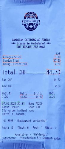
1. Convert PDF to JPG
Why do we need to convert the files to JPEG now? The thing is, we cannot just read PDF files in python and easily add bounding boxes to them. We need files that are in formats such as PNG or JPEG, so we can have document measurements in pixels instead of inches, as is the case with PDF files.
In our case, we used the fitz module from the PyMuPDF library as it’s pretty straightforward to use, even when we use it within our Azure Functions.
Completing this step means you have already converted your PDF receipt to JPEG and subsequently saved them into your drive. Note that if you’re converting a multipage PDF to JPEG, you will end up with more than one resulting file as JPEG doesn’t allow for multipage files.
2. Parsing the JSON file and extracting the coordinates of the bounding boxes
This is the most critical step to our mission, as without the coordinates of the bounding boxes it’s impossible to draw them on our images. Depending on the pre-built model you choose, your JSON file will be structured differently, so I won’t go into the details of how to find every data point inside your JSON Tree at this time.
The things you want to look for inside the tree structure:
- Number of pages in the PDF file
- PDF measures in inches (width, height)
- For each “field” (information of interest):
- Value
- Confidence
- Bounding box coordinates (8 points and in inches)
Great! Now you have the coordinates of every bounding box of interest and information about your PDF file that you will need to draw your bounding boxes.

3. Converting the PDF coordinates to JPEG coordinates
Remember that the bounding box coordinates we extracted in step 2 are in inches, as they come originally from the PDF documents the Form Recognizer analyzed. Now we need to convert those coordinates accordingly so that we can draw the bounding boxes on our new JPG files in the correct places.
To perform the conversion you need the following data:
- Bounding box coordinates from step 2
- PDF measures in inches from step 2
- JPG measures in pixels (width, length)
The pseudo-formula for the conversion is (coordinate in inches/side in inches)*side in pixel = new coordinate in pixel of our JPEG file. Remember always to consider if you’re making a conversion of a coordinate that describes length or width to adjust your formula accordingly. After being done with these steps you should have all your coordinates now in pixel values respective to the length and width of your JPEG document.
4. Drawing Bounding Boxes on the JPEG files
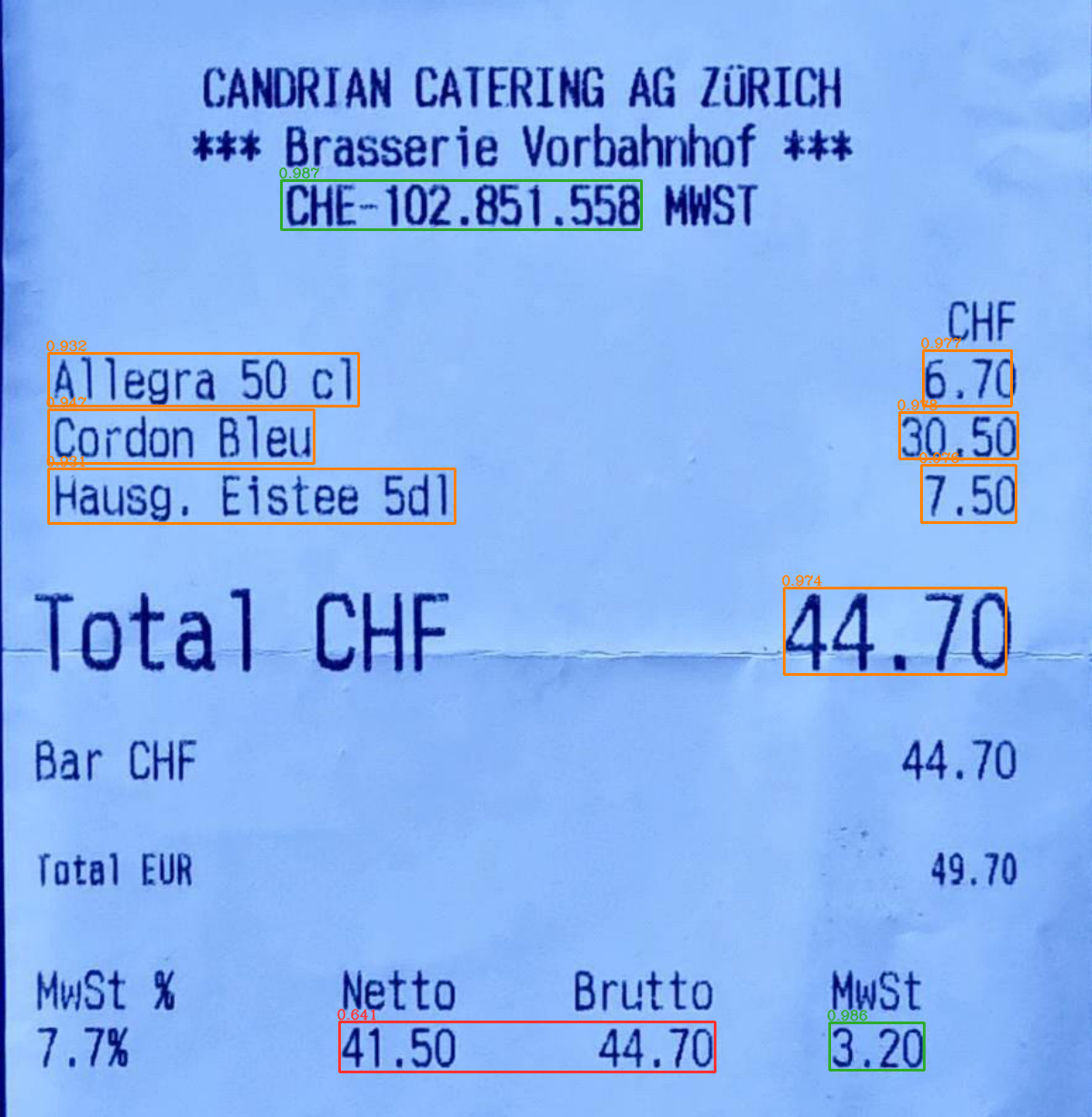
Now we can get to the last and most fun part, drawing the bounding boxes on the receipts. We already have the coordinates for all bounding boxes found by the model, with their respective value and confidence, and now is the time to put them to use. For this purpose, I used open-cv, a well-known library of computer vision applications.
To actually draw the bounding boxes one needs to read the JPG document from your disk into memory with the imread module from open-cv so that you have your image as a numpy array. After you have that array, you can iterate over all bounding boxes found by your model and plot them using the rectangle module in the open-cv library. This module is quite easy to use and only needs two x,y coordinate pairs to draw the bounding box over the image. Note: remember that the coordinates you extracted from the JSON file contain 4 pairs of coordinates. In this link, you can get some visual help to understand where the x,y pairs are located across your documents. You can use the coordinates of the top-left and bottom-right corners to draw your bounding boxes with the rectangle module. Using the same module, you can define the color of each bounding box. Something nice, in case you want to, for example, use different colors for different confidence intervals.
Optionally, you can use the putText module to plot the value or confidence on top of every bounding box.
Note: if you wish to use all coordinates to draw bounding boxes you only need to change the module you’re using and try with polylines instead. Your result should look like the image below.
Closing words
I hope by now you have an idea of one of the limitations of the Azure Form Recognizer when it comes to visualizing the results and how you can overcome them using python. In case you have any questions that I can help you with or if you are interested in this topic, please don’t doubt to ask.
One response to “Drawing Bounding Boxes from Azures’ Form Recognizer Results”
Thanks for the blogpost.
The formula to convert inches to pixels was just what I needed 🙂